I have moved my blog to a new location
Please go to http://jerrysrobots.com/b9/
Monday, April 27, 2009
Saturday, February 14, 2009
Brain Cup Finger Light Assembly
Brain Cup/Finger Light Assembly
As you can see from the left most picture the motor is attached to the motor plate using the rubber bushing to decrease the motor noises. The rubber bushings are trimmed away from the crown shaft opening so as not to interfere with the shaft rotation.
The key to assembling the finger lights is bending the music wire on one end so you can push the wire with 1 finger. Bend the other end of the wire slightly so as the wire advances straight through the drilled holes in the finger light tubes. It might help to sharpen or debur the wire on one end that is piercing the metal finger light rod to ease entry. I strongly recommend you use bulb receptacles from Mouser P/N 35LH010. They are T3-1/4 SCRW LMP SOCK Xicon Lamp Holders.


 Once you have secured the brain cup to the neck piece you can place the brain cam into the brain cup, adjusting its position to the desired finger light elevation desired. Lock down the set screw to the crown shaft and you are finished.
The finger light tubes and tips (a set of 7) is 50.00 plus shipping and Paypal fees. This does not include the lamp holders. The tubes are precut and drilled for the retaining wire. The finger light tips are machined aluminum.
Saturday, January 31, 2009
Replica Back Plate
 This is the Replica back Plate. It is made out of heavy duty fiberglass. As you can see it has the additional mounting holes where the dial lights are mounted to give it additional stability. It also has the "Ears" to keep the black out effect in the torso from coming through. This is a high quality part. It is used on the replicas that Mike Joyce sells for 25k. And the most important thing, it has the original hero design that is also symmetrical. A very nice and professionally made piece that makes your robot "sing". Craig's neon was the prototype for the plate so it should fit Perfectly. Also this should fit the Timk and Fred barton torsos as well without difficulty.

Wednesday, January 28, 2009
Torso Vents
Torso vents on the Hero robot were non movable except for the programming bay. Some even postulate that the ribs for the vents were screwed to the outside of the torso with wood screws. The Replica uses a static representation as demonstrated in the left picture below. In order to make my ribs movable but look like the setup on the hero robot I molded the screen vents to the inner radius of the vent. T hen I used Velcro to attach the screen to the top of the upper rail. That way the screen doesn't interfere with the vents. I used weed block material (for ventilation) from home depot as the black out material and attached that with 3M spray adhesive. I used a small amount of adhesive so it wouldn't leave a residue on the aluminum screen.
When installed, it looks just like the hero robot and just like the replica installation with 1 important difference. The vents are functional and allow full access into the torso. All you have to do is slide back the vent and then push or peel the metal vent off to gain access as necessary. When finished just push your vent back into place, close your vent and you are good to go.
I had tried bending acrylic to create a stand off for the metal screen but it always seemed to interfere with the upper vent rails. This solution was a very simple and quick solution. This is what it looks when it is fully installed. It took 20 minutes to complete all 3 vents.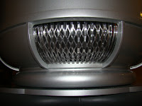
 hen I used Velcro to attach the screen to the top of the upper rail. That way the screen doesn't interfere with the vents. I used weed block material (for ventilation) from home depot as the black out material and attached that with 3M spray adhesive. I used a small amount of adhesive so it wouldn't leave a residue on the aluminum screen.
When installed, it looks just like the hero robot and just like the replica installation with 1 important difference. The vents are functional and allow full access into the torso. All you have to do is slide back the vent and then push or peel the metal vent off to gain access as necessary. When finished just push your vent back into place, close your vent and you are good to go.
I had tried bending acrylic to create a stand off for the metal screen but it always seemed to interfere with the upper vent rails. This solution was a very simple and quick solution. This is what it looks when it is fully installed. It took 20 minutes to complete all 3 vents.

Saturday, January 24, 2009
Crown Shaft
 I have 2 versions of crown shafts. They usually depend on the type of motor used and the brain cam design (this affects/determines the length of the rod and how it would be attached). The best attachment method is by recessed set screw so as not to tangle brain or finger light wires as the crown shaft rotates. The shaft to the left here is for the s
 maller motor used on the replica robot. The crown shaft to the right is used on the Hankskraft motor. It is shorter. Both are used on the larger delrin cam and can not be used on the Sanderson cam without modification.
Wednesday, January 21, 2009
B9 Replica Parts for Sale
Here are a few shots of the B9 Brain, Neck piece, Motor, Motor support and crown shaft


Here is the CAM and the final assembly with the finger light ends.


Here is the CAM and the final assembly with the finger light ends.


Monday, January 19, 2009
 It was a very sad day for me and many B9'ers and LIS fans across the globe to hear that Bobby May passed away. List servers lighted up that had been dormant for many weeks or in some cases months with the tragic news. I couldn't believe it myself. I had hoped to have Bobby up here at the B9 build off but now that wont happen but in spirit.
The last time I met Bob was on the second half of my honeymoon. My wife(Kip) and I were in Vegas attending a Star Trek convention. I saw Bob sitting at a table with his LIS banner but didn't have a robot with him. I asked him what he was doing there at a Star Trek convention to which he replied" "I had to add an air of respectability". LOL. Now, I ask you......Who could argue with that!!!! So I proceeded to help him crash the party and get a robot to the convention. I called Thomas (A fellow B9'er) up and he drove from California to Vegas and we got it set up for him so he could "bask" (ROFL) in his glory. Talk about club spirit and team work!!! And how about my wife Kip!!! She let me do all of that on our honeymoon too!!!! It was fun. We all had a great time and alot of laughs. I will always remember him that way. Lost in Space has a lot of special memories for me, especially the Robot!!
The following is an except from Bill Mumy's web site. I believe it portrays how we all felt about Bob May.
"Bobby May passed away this morning at the age of 69. He was my friend and my coworker and he was one of the hardest working guys in show business that I ever knew. He managed to create a classic TV personality out of a claustrophobic fiberglass prop that he was crammed inside of for over three years. He memorized 40-50 pages of dialogue each week for 84 episodes and delivered it with passion and rhythm while all the time knowing that it would eventually be re-recorded by Dick Tufeld.
I never heard Bobby say a bad word about anybody. He had a laugh that was loud and infectious. He called people "Buddy." He knew hard times and he knew easy times. He was a loving husband, father and grandfather. Bobby was a one of a kind who truly brought soul to the Robot on Lost in Space. He loved playing the Robot, and he loved all the fans of Lost in Space. He traveled all over the world meeting fans and attending conventions. When the series was originally on the air, Irwin Allen, the creator and executive producer, wanted people to think the robot was real, so Bobby received no billing or credit for his hard work. It wasn't until many years after that Bobby started to get recognized for his amazing contributions to the show. I was happy to see him get the credit he deserved.
I enjoyed working with Bobby when I was a boy, and I enjoyed working with him and seeing him and his loving wife Judy as a man. Bob and I spoke several times in the last month, and although I I knew that he was going through some serious health issues as well as having lost his home and all his possessions in a recent fire, Bobby was positive about the future. I wish him well and send him positive energy and love on his new journey. I'm sure Jonathan Harris is insulting him right now! "Silence, you ninny! Cease your prattling you cluttering clump! Oh, the pain! The pain!" -- Bill Mumy
Thursday, December 18, 2008
Radar
This Radar is the latest version and is what is going on my replica torso and is correctly resized to fit the replica collar and Torso. (the club collar is 4" thick the new size is 3.625" thick (and a little narrower). As you can see with this picture, the clutch pack has a tapered top. A top view shows a milled out key area for the bubble lifter (never mind the slight dent off to the right of the key - it was a mistake but it will be covered up with the bubble lifter cover so it doesnt matter. Also note the 2nd half of the radar has upper and lower base plates where the ears are inserted.


And of course here is the Bubble lifter tube with the key inserted. I have included the drawing
so you can assemble your own.


Underneath the radar unit I have places for the motor drive unit so the radar can be turned remotely or automatically as well as places for the electronics for the ear sensor motors.


And of course here is the Bubble lifter tube with the key inserted. I have included the drawing
so you can assemble your own.


Thursday, October 2, 2008
Arm Design
 Here is a brief overview of the B9 arms for my robot
Basically they will move out using a drawer slide and 6" actuator remotely. The arms can move independently of each other. Then the Dewert motors will be activated to move the arms up and down (approx a 40-60 degree sweep). Using the arm with 12v power is too slow when compared to how Bob May moved his arms in the show. 24v yielded a much closer and safer facsimile.
Thursday, May 22, 2008
The Great Texas B9 Build Off
Well, The Great Texas B9 Build Off of 2008 (May 16-18) seems to have been a success! I loved it. I learned so much and it was so refreshing to see so many different types of robots in 1 place and to see how they were constructed. It was mind blowing. There were members from the B9 Club, the R2 Builders Club and the Dallas Personal Robotics Club as well as visitors young and old. Some of them stopped buy as we were setting up on Saturday morning wondering if they could buy any of them. I think they thought we were having a garage sale……
There were B9’s, R2's, R5, Battle Droid, Pit Droid, Mouse Droids, Insectoids, a C-3PO needing plating and a Fred Barton Robby the Robot all in 1 place. And let’s not forget the Laser rifles, a working MP41A Pulse Rifle, Light Sabers, Phasers, Tricorders, Communicators and life size mannequins of Dr. Smith & Will Robinson, not the least to mention a full size, working, Jupiter 2 center flight console with a Burroughs B205 console on top! And if that wasn’t enough we got to see a 1966 Batmobile in construction. MAN is that thing BIG!!!!! You need a Batcave to house that thing!
We had a few participants take advantage of the Machinist and Painter I had reserved for this weekend. We had B9 torsos painted and R2 & B9 parts made just for this event. Lots of goodies for everybody and there was parts everywhere! Lovely…..machined……anodized…aluminum parts….Did I mention they were machined and anodized….???
Since this was a build off I had to go ahead and announce “Build your Robots”. It was like Christmas. I saw people tearing into boxes and sanding and making frames for the Astromechs. When you have multiple palm sanders going it kind of sounds like model airplanes flying around and that definitely drew attention from my neighbors. They loved it. (Not to worry, I had informed my entire block that this was occurring). They had their kids out and about looking and poking at everything. I still have a smile on my face!
My machinist even helped out a fellow builder because he wanted to make one of his own and this was “good practice”. Wayne Orr replaced his Omni Balls with Casters. My R5 did his debut at the build off. Wayne’s R2 and my R5 had a little race in the back alley…… Three aluminum R2 Frames were built. Travis Jeter finally got those holes drilled by the master himself, Mike Joyce; and finally got his bubble attached! Bob Greiner and I also fixed his waist motor mount and drive.
All in all everybody had an excellent time. The food was great! Anybody and everybody that wanted or needed help got it. We even had a little strategy meeting on how we were going to help who and when so everybody could get taken care of.
There was also 3 very important lessons that I took away from the build off. Never drive your B9 when you are tired, 2) never stack your robot with parts that are not secured and 3) always remember to turn off your receiver before you turnoff your transmitter.
What happened was on Sunday morning I had my collar and radar unit placed on my replica torso. While I was talking to a friend, I was switching my transmitter to operate another robot I had (my R5D4). When I did that, and because I didn’t turn off my receiver before switching robots and my B9 leaned over and dumped my collar and radar section onto the hard concrete, shattering all of it into little pieces. The act of the collar coming off also scratched the neon mouth opening on the replica torso. Oh, well; as Mike Joyce said, you cant make a few robots without breaking a few parts……
Monday, March 3, 2008
B9 Build Off May 16, 17 and 18th 2008
 The weekend of May 16th I am hosting a B9 build off at my home in Rowlett, TX. I hope to get a decent amount of participation from the B9 builders club with local involvement from the Dallas R2 builders and the Dallas Robotics group for those interested in the B9 as well.
Here we will be building, assembling and painting B9 robots. I have a machinist reserved for the weekend exclusively for the build off as well as 2 painting houses. So if you come prepared you could walk away with a completed robot. What an opportunity!!!! Bring out those B9's from the garage and get them functional!!
We will also be filming interviews of fellow builders with their stories as well as instructional "how to" videos on topics like basic construction techniques and materials, electronics, prep and paint, weathering, puppeteering, safety and other topics as requested. We have a lot of big names in the B9 and R2 word scheduled to attend. So please mark your calendars and come on by. Go to the B9 builders website on yahoo at http://www.b9robotbuildersclub.com/ for further details, agenda and location. I also included an area map for those needing hotel rooms. It is all FREE. Saturday evening will be a dinner (Texas Style of course) so I will need you to RSVP for that,
Here are but a few of the tentative speakers/guests: Mike Joyce, Tom Jozwiak, Charlie Garcia, Craig Reinbrecht, Phillip Hamilton, Bob Griener, Ken Pringle, Wayne Orr and Guy Vardaman from the R2D2 Builders group. The list keeps growing. So do yourself a favor and come on down! You won't want to miss this!!!!
Sunday, March 2, 2008
Machining Parts - What's it all about & Why is it so expensive?
I thought it would be a good idea to enlighten those uninitiated into all of what happens in the making of a machined part. I found it a fascinating and an illuminating process. Not realizing or appreciating what looked so simple, even automated, could generate so much work and such an expensive price tag. So many times we get sticker shock from what we thought was an easy or automated process and wonder what is going on. Are we being taken to the cleaners? It can certainly feel that way at times but the reality is making "1 off" parts is a very expensive endeavor. You need to understand and accept this to be prepared if you are going to take my plans (or anyone else's) to your local machinist to do some work. So lets start off with an FAQ of sorts about getting parts machined and then we will work out a concrete example from this build so you will understand what I mean.
***Disclaimer***: I am not a machinist nor do I play one on TV (or work for one). The experiences described below are from my personal experiences/lessons learned from dealing with several machine shops both local and distant (out of state) to the DFW area. This discussion is designed to help you understand what you are getting into and is not to be considered the only or definitive authority on the subject. Your experiences/mileage may vary. Lets start off with what you will be faced with when dealing with most machine shops.
Machinist Expenses
Setup Fees - The cost of entering measurements or dimensions into machines, etc. There is usually a minimum charge that shops assess. For example, TAP Plastics charges a 250.00 minimum fee for anything cut on its CNC machine.
Material Fees - The cost of the material used in its raw state
Machine & Labor time - Time charge for machine operation & operator monitoring/adjustment
Sub Contractor fees - Using other shops for completion like anodizing or welding parts together.
Shipping & handling charges - self explanatory.
Taxes - self explanatory.
Machine Shop Expectations from the Customer
Clear, complete communication. He will only do what you tell him to do. He doesn't read minds!
When you come into a machine shop you should know "what" and "how many" of a given item you want made. You also should know what you want it made out of like aluminum, plastic, steel, brass, etc). Not having or knowing this information puts the machinist in a consultant capacity. His time is Money. Don't think for a minute that he wont charge you to discuss how to do something if you do not already know what needs to be done. A good machinist SHOULD discuss what you are wanting done but don't go in there with the expectation that he is going to figure this stuff out for you for free and then only bill time and materials to make it. This is why a lot of machine shops will not deal with hobbyist for "1 off" projects or why requests of this nature are routinely done when there is no other work available.
You need to have clear, accurate drawings with exact measurements clearly identified. They do not have to be CAD drawings but those are the best to eliminate confusion and mistakes.
It usually does not matter if you have CAD drawings in a computer file or not. Good machinists can take a pdf or print outs of some type and work with that as well. However, no matter what you have as a reference, there will be a degree of human involvement required to get that information from the source into his machines and this is where the setup fee is based. In some cases the setup fee can be more than the cost of the material and labor combined to produce your part. The "key" to keeping your costs down is by dealing with a machinist that has already done the setup for this part if at all possible.
What is a "1 off" part or project? Quiet simply it is the making or the machining of any part or assembly where there is only a quantity of 1 involved. For example, A left and right hand version of something is still considered 1 item. There could be 40 different components to be made in the assembly of 1 item. That is still considered 1 item. This is the most expensive cost per item there is. Often, if you inquire, you could get multiples of that item you are making for only a fraction of what you had to pay for just 1. This is the basis for doing "runs" of parts so that others can benefit from the lower cost and availability.
Also, some shops will require you to put down 50% of the expected charge before they will begin to schedule or perform any work.
Customer expectations from a Machine shop
Clear, complete communication - Don't assume anything! Ask a lot of questions!!
Clear explanation of rates/fees - Make sure you ask for a detailed billing/charge list of services.
Authorization before action - No Shop should just go blindly ahead unless you authorize them.
Detailed billing - A complete, clear and accurate listing of item, cost, time and quantity.
Approval before payment - You need to make sure you are happy with it before payment. The
shop should work with you if there are any issues with quality or quantity of work performed.
Delivery Promises - Discuss at the very beginning any time lines you need to hold the shop to and make an agreement with them what will be done if they fail to meet that promise (like a discounted rate). Get it in writing. Shops have been known to do what is in their own best interests but if what you are contracting them for is time based they need to know that up front and that what they have or have not done maybe at risk if not delivered as promised. Recognize that some shops will not do business with an individual this way. That may be your clue to take your business elsewhere. You need to be reasonable when negotiating on this point.
A Practical Example:
Lets take the original aluminum waist plate I made for my B9. It started out as a block of solid 25 lb sheet of aluminum. The outside configuration/drawing was a copy of the PVC version of the waist plate that Andy Schwartz currently sells. The plate of raw aluminum currently runs at approx 4.20 per pound for 6061. It took (with a CAD drawing as a reference) 1hr to input those figures into the CNC machine. Most shops charge between 60-75/hr to do that. While the CNC machine is cutting the aluminum the CNC operator must monitor the process to watch out for broken bits, misalignment or other errors. Then he has to take that device out and flip it around and restart the process all over again to complete the project. That cost me 225 for time and 125 for materials equaling $400.00 dollars.
Now take that 1 step further and lighten that same waist plate. Instead of having dozens of data points to enter into the CNC machine, you now have hundreds of data points to enter into the system. All having to do with length, height, width and depth. The additional programming to do the diet version required 3 additional hrs of programming. To do all of this 1 time would of cost you $825.00 for 1 waist plate.
As you can see, the amount of time expended for that 1 waist plate makes it very costly. Now if you made more than just 1 of those waist plates the setup would only need to be done once. The other copies would only incur material and time charges, in this case it drove subsequent diet waist plates prices all the way down to 425.00 each; which is the price you would pay now.
I hope this makes sense to you and allows you to further appreciate what I have done for the club (for these parts) and the beauty of mass production.
B9 Electronics: The Inside Story Part 6 - the Finger Lights, Brain & Crown Animation
 As I was using the light controller from Tom for the belly and chest lights, so to am I using another board from Tom for the finger and brain lights. It's basically the same board as the chest and belly lights controller card used in the Torso. The reason I used another one was so that I could get a different blinking and pattern rate than the torso. I wanted an asynchronous blinking pattern between the 2 sections. To me this gives a more realistic appearance of a real, functioning robot. Just as a side note, you could hook up everything to 1 controller card but I wanted that certain, special, something that only 2 cards can provide.
The crown and finger light movement is handled by the Hankscraft 12v 7rpm motor. You can obtain this motor from a number of sources and is readily available. The average price for this motor is 25.00. What I had a problem with was the wires coming out of the brain and finger lights passing through the brain cup into the neck. As you can see from the picture on the left from the B9 website, there isn't much room and I had to remove the wire sheaths and drill out additional wire routes to go around the Hankscraft motor. It is a VERY tight fit. Take care not to kink the thin wires coming out of the finger lights.
Saturday, March 1, 2008
B9 Electronics: The Inside Story Part 5 - Radar Section
 My radar section uses the B9 creations' 2.5v regulated power supply and the Namiki Ear Motors for the ear sensors. Both of which were obtained from Eric Johnson from the club website. The Namiki motors are very sensitive to voltage and you can burn them out easily. The radar is moved by a digital robotic high power JR servo (JR DS8711). The range of movement is 180 degrees. 90 to the left and 90 to the right. I can fit a 360 degree servo in there or I could use a sailing wench servo for continuous rotation but most shots from the series do not show the radar moving greater than 90 degrees because the rotation of the radar section was controlled by Bob Mays head movement, so I decided to stick with that. I would suggest that you use a geared motor to rotate the radar section if you want to have 360 degree movement. However, in order to do that you would need to have a motor controller to be able to direct the degree and direction of rotation. That just means more money and more stuff to cram into the collar/radar area.
I also experimented with IR (infrared) sensors in the collar to direct movement of the radar when the robot is in animatronic mode to further simulate AI (artificial intelligence). The device I used was from Jim Shima's website called Hyperdyne and Hotcranium.com. These are the same controller cards that the R2D2 group uses for automatic dome rotation in relation to sound and IR movement detection. It works most of the time so long as you are not in a very loud or hot room. That is not always possible at a convention. Also, since the detectors are in the collar you have to be at least 48" tall for it to detect you. So what I decided to do was put in a IR detector in the rear vent bay to detect those pesky little carbon based replacements we call children. When it detects someone close it triggers a voice message saying to please stand clear and to step away from the rear vent and power pack.
B9 Electronics: The Inside Story Part 4 - The Torso
There is a lot of stuff that goes in the torso so lets start with the most basic question. Where is the power coming from and how will you split up or handle different voltage requirements for all of the electronic gadgets inside the torso? The answer is this: A 12v 12ah gel cell battery in the torso & a few 12v distribution boards. Now before we go any further let me say that I thought of using a slip  ring to bring power from the tread section to the torso but I had to rule it out because of the way I am doing the hip rotation. The drive is off center and has an over sized gear cog which obscures the center of the CSS. I did look at the figure 8 procedure to accommodate such situations but However I still want to be able to do a 360 rotation. This defeats the reason for a slip ring. I also though
  of running wires up from the base and then have enough slack to be able to handle several 360 degree rotations but I just didn't feel the need for that. Most of the time I will not be doing a 360 degree rotation of the torso.
The distribution boards were originally created for the R2D2 builders group by Dan Stuettgen. I convinced Dan to change his board to include a few 3.3v connections for both rows of teeth lights making them more suitable for our club. Those boards should be showing up very soon. The additional change will also help the R2 group for those wanting the USB powered devices so this change helps everybody out (don't you just love inter-club cooperation)!!
 ring to bring power from the tread section to the torso but I had to rule it out because of the way I am doing the hip rotation. The drive is off center and has an over sized gear cog which obscures the center of the CSS. I did look at the figure 8 procedure to accommodate such situations but However I still want to be able to do a 360 rotation. This defeats the reason for a slip ring. I also though
  of running wires up from the base and then have enough slack to be able to handle several 360 degree rotations but I just didn't feel the need for that. Most of the time I will not be doing a 360 degree rotation of the torso.
The distribution boards were originally created for the R2D2 builders group by Dan Stuettgen. I convinced Dan to change his board to include a few 3.3v connections for both rows of teeth lights making them more suitable for our club. Those boards should be showing up very soon. The additional change will also help the R2 group for those wanting the USB powered devices so this change helps everybody out (don't you just love inter-club cooperation)!!
The Torso Lights
Lets start with the belly lights. I have the lighting kit by Tom Wisnionski for the belly and chest lights. This kit is not for the faint at heart! There is something to be said for just doing basic wiring of the lights with flashing bulbs (but I have never been known for doing what's easy! ) This kit allows you to vary the blinking pattern and speed of the lights. This kit uses 6v bulbs. I put 6 volt bulbs in the brain, chest, finger and belly lights. It requires a degree of intense wiring but the instructions are (for the most part) clear and easy to follow.
Lets start with the belly lights. I have the lighting kit by Tom Wisnionski for the belly and chest lights. This kit is not for the faint at heart! There is something to be said for just doing basic wiring
 of the lights with flashing bulbs (but I have never been known for doing what's easy! ) This kit allows you to vary the blinking pattern and speed of the lights. This kit uses 6v bulbs. I put 6 volt bulbs in the brain, chest, finger and belly lights. It requires a degree of intense wiring but the instructions are (for the most part) clear and easy to follow.
 The Dial Lights (chest lights) and the programing bay light hook up to Tom's board as well.
The teeth lights use the NKK lighted switches part number 633-215kkw016b1jb-r0 at Mouser.com. Those are the ones used in the replica robots. The lighted portion of the switch requires a 3.5v power source so be careful you DO NOT go above that. If the LED blows in this switch you need to get another switch because the LED's can not be replaced; and at 22.95 each that can get very expensive, very quickly.
The Neon
 The neon that I use is the 16 row neon that was sold by Craig Reinbrecht. Craig only sells the 12 row neon now. Another vendor (Dennis Wilbur) sells a 12 row neon as well. Mine is connected to a Tech 22 model 8000 neon power supply (which needs 12v to operate correctly). While we are on the subject, let me show you the correct way to connect the 2 neon halves.If you look on the B9 website Craig has a diagram on what to do but his example shows a 1 piece neon. As you can see the wiring of the neon is like 1 continuous loop for the 2 halves. However describing it just isn't enough. It helped me to actually see what it looked like. So here it is.
I also discovered that soldering the high voltage wires to the neon is not a very good idea because the heat from soldering can damage the neon. It is best if you just use wire nuts.
Also, when testing the unit if you get a strobing effect or a flash of light then it is most probably because the wire leads you are using are too long. Neon is very sensitive to voltage and resistance. I have found consistently that if use VERY short test leads you will get a successful test. But in any event you should test each section of the neon firs t to make sure it lights up well. Then when you connect the 2 together the length of the test wire leads will make a tremendous difference in a successful test or not. It would be best if you would use the special high voltage wiring because your 12v power source is generating 8,000 volts. If you see a "beading" of neon then you will need to use the supplied diodes to correct that. Make sure you only apply the diodes to the upper section of the neon. Please note that there is a solid black line that denotes the orientation or flow of electricity through out the neon. Please make sure you have the correct orientation of the diodes or the beading may still continue.
Also, when testing the unit if you get a strobing effect or a flash of light then it is most probably because the wire leads you are using are too long. Neon is very sensitive to voltage and resistance. I have found consistently that if use VERY short test leads you will get a successful test. But in any event you should test each section of the neon firs
 t to make sure it lights up well. Then when you connect the 2 together the length of the test wire leads will make a tremendous difference in a successful test or not. It would be best if you would use the special high voltage wiring because your 12v power source is generating 8,000 volts. If you see a "beading" of neon then you will need to use the supplied diodes to correct that. Make sure you only apply the diodes to the upper section of the neon. Please note that there is a solid black line that denotes the orientation or flow of electricity through out the neon. Please make sure you have the correct orientation of the diodes or the beading may still continue.
 The Bubble Lifter
The bubble lifter uses a GWS777 6BB Robotic servo. This servo can lift over 20 lbs but only if the servo is externally powered with a 6v battery or some other power source. Th is amount of power is necessary to lift everything above the radar section and be able to move it up or down quickly. A fast bubble movement is imperative if you are to replicate the synchronous of bubble "attitude" when the robot when asking or saying certain phrases. The auxiliary power device that the GWS servo would plug into is shown in the picture to the right.
 is amount of power is necessary to lift everything above the radar section and be able to move it up or down quickly. A fast bubble movement is imperative if you are to replicate the synchronous of bubble "attitude" when the robot when asking or saying certain phrases. The auxiliary power device that the GWS servo would plug into is shown in the picture to the right.
The Sound System
I decided to use the CF3 sound system by ACS Control Systems Inc. It is the sound system I use in my Astromechs. These typically run around 179.00 plus any additional IO input car ds, sand cards and external power supplies if your robot uses AC power only. It is a beauty and easy to use. It can handle as many as 48 contacts (which is what mine has) that can trigger various sounds and contact closures remotely, automatically or in response to other contact closures, IR devices (a
 ctive and passive), etc.. It has an interchangable SAN card that can hold any amount of sounds files wether they are WAV or MP3. It even has a scripting routine along with background files that can be played (the robot sound).
To trigger sounds without the need of a computer I included a couple of 12 channel RF remotes from Cold Fusion to activate those sounds while he is mobile. These can be found on eBay for as low as 24.95. This is a great little remote that has a teriffic range (500 feet unobstructed). So my robot could be way ahead of me and he could respond to the crowd and no one would see who is controlling him.
 ds, sand cards and external power supplies if your robot uses AC power only. It is a beauty and easy to use. It can handle as many as 48 contacts (which is what mine has) that can trigger various sounds and contact closures remotely, automatically or in response to other contact closures, IR devices (a
 ctive and passive), etc.. It has an interchangable SAN card that can hold any amount of sounds files wether they are WAV or MP3. It even has a scripting routine along with background files that can be played (the robot sound).
To trigger sounds without the need of a computer I included a couple of 12 channel RF remotes from Cold Fusion to activate those sounds while he is mobile. These can be found on eBay for as low as 24.95. This is a great little remote that has a teriffic range (500 feet unobstructed). So my robot could be way ahead of me and he could respond to the crowd and no one would see who is controlling him.
Arms and Claws
Now you may have noticed that I conspicuously left out the motorized arms and claws. This will be a surprise that you will only see at the build off. I will show you the customized controller board that I had made but that is it for now.... muhahahahahaha ..oh sorry...that was my Dr. Evil laugh coming out.... :)
Now you may have noticed that I conspicuously left out the motorized arms and claws. This will
 be a surprise that you will only see at the build off. I will show you the customized controller board that I had made but that is it for now.... muhahahahahaha ..oh sorry...that was my Dr. Evil laugh coming out.... :)
Thursday, February 28, 2008
B9 Electronics: The Inside Story Part 3 - Leg, Hip & Waist
OK, fair warning now... the further we go up, the more complicated the electronics become... sort of...Again, this is what I did. There are several ways to "skin a cat" and this is one of them......
My hip section moves up and down to simulate a power failure from a power pack pull out as well as to bow to pick things up, address royalty, etc. The motor to rotate the torso is also located in the hip section. This is a departure from Mike Joyce's replica robot where the waist rotation motor is actualy inside the torso. The motors used for both the hip and waist rotation is the Dewert 24v motors. Each one is controlled by a Vantec RET 411P single motor controller . These plug in to the RC receiver. I fused each RET 411p to protect it from any overload or spike from the batteries, etc. The manual for the RET 411P is located on the Vantec web site at http://www.vantec.com/retman98d.pdf. It is a very straight forward wiring procedure where the positive and negative leads of the motor are connected to the white and gray wires of the vantec controller. The black and orange wires go to the positive and negative leads of the battery. Note where the switch goes. I will use one of the switches inside of the programming bay to control hip and waist rotation. By switching them off I could save on battery power consumption and also serve as a safety control mechanism if I wanted to limit movement of my robot.
My hip section moves up and down to simulate a power failure from a power pack pull out as well as to bow to pick things up, address royalty, etc. The motor to rotate the torso is also located in the hip section. This is a departure from Mike Joyce's replica robot where the waist rotation motor is actualy inside the torso. The motors used for both the hip and waist rotation is the Dewert 24v motors. Each one is controlled by a Vantec RET 411P single motor controller
 . These plug in to the RC receiver. I fused each RET 411p to protect it from any overload or spike from the batteries, etc. The manual for the RET 411P is located on the Vantec web site at http://www.vantec.com/retman98d.pdf. It is a very straight forward wiring procedure where the positive and negative leads of the motor are connected to the white and gray wires of the vantec controller. The black and orange wires go to the positive and negative leads of the battery. Note where the switch goes. I will use one of the switches inside of the programming bay to control hip and waist rotation. By switching them off I could save on battery power consumption and also serve as a safety control mechanism if I wanted to limit movement of my robot.
Wednesday, February 27, 2008
B9 Electronics: The Inside Story Part 2 - Soil Sampler
 For those using my version 1 drive section (for robots 300 lbs and under) and you have the B9 Creations soil sampler and are using Eric's tread sections, this is the only way to install it. There are some
  modifications that you will need to make to the face plates of the sampler so it will mate correctly with the drive section. Once
 this simple and easy modification is done it will fit perfectly. If your robot will be over 300 lbs then you will have to go with a more powerful drive section. Since the version 2 drive section has bigger and more powerful motors the existing soil sampler by Mike Joyce will not fit. I could hack up Mike's existing frame and still use his internals but I decided to design a new soil sampler because Mike no longer offers a soil sampler. I will also add some new capabilities to the soil sampler. Like actually being able to obtain a soil sampler (what a concept). This one will have 2 settings. 1 for indoor "show" use. That setting will allow the sampler tube to come out to the floor, spin and retract like the original. The 2nd setting will actually extend the sampler tube to go below the level of the floor and drill down into the ground. I thought it would be nice for the environmental robot to be capable of actually doing his real/stated job. In order to accomplish this I will be using a 24v power drill motor with clutch. The 2nd setting just extends the sampler an additional 6". There is also a small suction tube/vent in the drill tube assembly to aerosolize the dirt for analysis.
 B9 Electronics: The Inside Story Part 1 - Tread Section
The electronics of a B9 can be as simple or as complicated as you want to make it. To assist me I visitied (several times) http://www.instructables.com/id/Circuit-Building-101 to boost my electronic knowledge and skills. There are a lot of sites like this one but I wouldnt let my fear or lack of knowledge hinder me in getting my robot to do what I want him to do. After all, WHO is the master here? Me or him??
Well, anyway, to facilitate this blog discussion I will be going over various systems in am or will be using in my robot. Because this is usually a touchy and potentially complicated subject I will be dividing it up into several parts. As a single point of reference the RC transmitter and receiver I am using is the Spektrum Dx7 with the AR7000 receiver with fail safes set (at binding) to zero forward velocity, forward hip set to "slump" and contact closure set to announce "Warning, Warning, remote control connection lost".
DRIVE SECTION
What makes a B9 go? Money....I mean Motors. BIG Motors! See the heading called "New Drive Section" below. Two (2) NPC Br81 and Br82 24v wheel chair motors with Two (2) 6" 65 durometer rubber wheels for traction and shock absorption. Two (2) Gel Cell 12v 33ah  ("Marine" or "Deep Cycle") batteries, plenty of 10 gauge stranded wire and a Vantec motor controller RDFR23 along with a 24v DC power supply (yes, you can plug him in and drive him around with a really long extension cord if you had to).
 ("Marine" or "Deep Cycle") batteries, plenty of 10 gauge stranded wire and a Vantec motor controller RDFR23 along with a 24v DC power supply (yes, you can plug him in and drive him around with a really long extension cord if you had to).
 I started by wiring the two (2) 12v batteries in series to achieve 24v. You do that by taking the positive of 1 battery and connect it to the negative pole of the OTHER battery. Once that was done, you attach wires to the unused poles of the 2 batteries and connect them to a central, resettable fuse block and distribution panel in the left tread section. [I originally had this area in the hip section but then realized how much of a PIA it would be just to reset a blown fuse (pulling the torso off and resetting the fuse would require at least 2 people probably 3, etc)].
 The Vantec controller connects to the RC receiver with 2 servo like connections; 1 marked with a "T" for throttle and another with a "S" for steering. Plug those into the corresponding slots on the receiver and you are ready to learn how to drive your "bucket of bolts". [As a side note make sure you do not adjust your power curve for forward or reverse throttle. Try it out at its default setting first. You don't want your "bubble headed booby" popping wheelies or doing somersaults!] The website for the Vantec Manual is this: http://www.vantec.com/RDFR21%20Manual.pdf Take a look at that as it gives you detailed information on how to setup your controller for proper operation. I will also wire in and use one of the switches in the programing bay to turn off the motors for safety reasons and to concerse battery power.
Because the soil sampler will be in the right tread section, you want to take into account that a power feed will need to go to that tread section. Do not forget to put a fuse in line for the soil sampler. Also, the soil sampler is powered by a 12v 3 rpm motor. Since my power system is 24v I have to either draw off of 1 12v battery (which isn't recommended because it will cause an uneven drain on your primary batteries) or have some load balancer in place. The other obvious option would be to have a separate 12v battery that could be used for the bulb lights, neon and sound amplifier. I will option for a separate 12v 12ah battery. This should give me a full days capacity at shows and special events (I am only looking for 8 hrs of use). There was another consideration. I could change the motor of the soil sampler to a 24v geared Tsukasa electronics company motor. I seriously thought of that but then considered the issues with the lights in the torso and a further breakdown from 12v to various other voltages. I found a power distribution board that starts with a 12v source. It breaks down voltages for your RC receiver and other components like the 3.3v for the teeth lights, 6 volts for the belly, finger and brain lights and 5 volts for the RC receiver. Therefore I opted to stay with a separate 12v battery that I will keep in the CSS by one of the vents (so I can R&R quickly or just charge it easily).
CAD Drawings of my B9
 The CAD drawings that so many of you have asked me about are rolling in now. This should allow you to have them made at your local machine shop or allow you to make them yourself. There are over 100 drawings and at $25.00 a page you can figure out how much it costs me to have them drawn up.
 As soon as I have all of them I will send out an alert to the group. I think this is the first step in getting standardized drawings that fit with established club produced parts. As I have mentioned in previous club posts, these plans are for club use only. If you use them then you are agreeing that you are using them for yourself only and will not take these plans to form any commerical or financial venture without my expressed written permission. I own these designs. They are copyrighted. I am spending a lot of money having these professionally drawn for the benefit of the club. Please do not abuse this gift! I will accept donations for them but I will not demand a charge for them unless you require them to be physically sent out or mailed. There is a PayPal donation button at the top of this blog for these drawings. Let me know what you think about them and if you require something that I may not have.
Sunday, February 24, 2008
The Bubble
 Without a doubt the best production bubble I have seen has been Fred Barton's. It is nice and clear but thin and easy to damage. In addition, Paul Felski's bubble from "across the pond" is also very nice! It's good to have quality vendors that allows you a choice for parts. I got to meet Paul last year at ROBOCON 2007 and had the opportunity to look at his bubble from his B9 pictures. I chose Fred's since I am state side. Someday I hope to meet Fred as I hear he is an interesting character!
Anyhow, back to lessons learned....don't bring the bubble out until you are ready to install it. If you leave it out, curious hands, house keepers and other family members will make their way to it where they find out just how light and fragile it is so take it from me ...put it away in a safe, hidden place till you are ready to install it.
When you are ready to start drilling holes in the bubble make sure you "key" the bubble. Mark the front of the bubble with some blue painters tape. Make sure you tape/mark the front of the top and bottom part of the bubble.
Another thing I learned is that it helps to use a special drill bit when making the holes for the lower lid and brain cup holes. The drill bit needs to be made for plastic drilling (yes there is such a drill bit). Drill bit #40 and #50. You can get them at McMaster-Carr.com. When I received mine from Fred, I had to open up the center hole for the neck bracket (just a little bit). Take your time with this. Mike Joyce was kind enough to offer this procedure for fitting the bubble:
Carefully mark the location where you want the 4 holes on the bottom plate (I say four because the original had four.) Drill the 4 holes in the bottom plate slowly using a standard #50 drill bit.Tape the the bottom plate to the bubble using masking tape, etc. in the exact position you want it (centered). Be sure to mark both the bubble and the bottom plate "Front". Put tape on each, etc. Match drill the 4 holes in the bubble using the bottom plate as a guide and again use the #50 bit. Remove the bottom plate and enlarge the 4 holes with a #40 drill bit. Use a counter sink bit on the bottom plate as required for #2 flat head screw to set flush. Attach the bubble using four #2 x 1/4" screws. These are McMaster Carr part number 90006A077. The original used these small screws as well.
Stay tuned for our next episode: "Electronics of the B9. The inside story"
B9 Brain, Lights and Crown
 The B9 Brain was from Scott Sanderson. The basic body was copper coated to hold paint better when I received it. I got some white transparency material and sprayer the frost mist from any crafts store to serve as a diffuser for the brain lights. I also sprayed the frost in the brain eyes to give it that same look from the show. Inside I have Tom's brain light kit. His kit has clear LED's. I took some magic markers and colored the LED's for a special, different effect. The beauty of this is if I don't like it I can wipe them off and I am back to the standard B9 white lights.
I also like the LEDs because they only require 6 volts and do not produce any notic
 eable heat. That is very important so over time my bubble wont glaze. In addition, something not every B9'er seems to know is that the top of the brain is mirrored. So I had my lid polished to a mirror finish. I thought about chroming it but I think I got a good enough reflection to get a good effect when the crown is moving and when the upper lights are blinking. You be the judge.
The crown was from Bill Kendzierski. It is a highly polished stainless steel work of art.
Subscribe to:
Posts (Atom)
